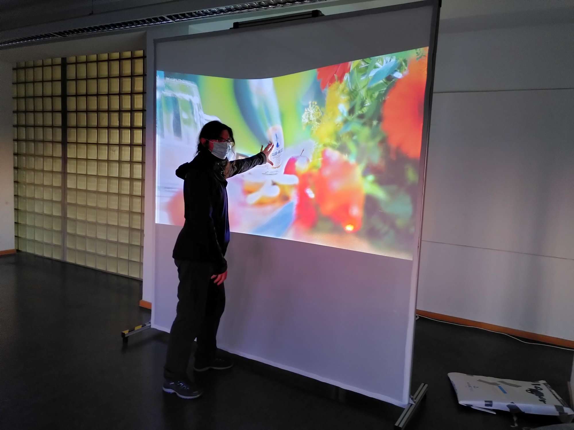
Interactions result in a stream of depth images.

Why is tracking needed on an elastic display?
With the help of tracking we determine the positions, the depth and the type of interaction on the elastic display.
Can you briefly describe the tracking setup? What is particularly important?
Below the surface of the elastic display is a depth camera, e.g. an Azure Kinect, which optimally captures the entire touch surface. In order to avoid recalibrations, a stable and secure positioning of the camera is very important in practice.
Why did you choose tracking with depth cameras?
The camera works on the Time-of-Flight (ToF) principle by emitting light in the near infrared spectrum (NIR) and measuring the time until the reflection of the light arrives again. This allows for direct and fast calculation and transmission of the depth map independent of interfering light, i.e. light that is outside the infrared spectrum. The image projected onto the surface of the elastic display, texture and color of the surface thus do not influence the tracking.
Are there significant differences between currently available depth sensors in technological aspects?
Basically, there are two approaches which can be used for tracking the surface deformation of Elastic Displays:
- Time-of-Filght (ToF) sensors (Kinect 2, Azure Kinect) constantly emit infrared light with modulated waves. They measure the time emitted light takes from the camera to the object and back by detecting the shifted phase of the returning light.
- Pattern Projection (Kinect 1, Intel RealSense) project a known infrared pattern into the scene and compute depth based on the distortion of the pattern
(more information: Comparison of Kinect 1 and Kinect 2 sensors)
Usually, also stereo-cameras (e.g. StereoLabs ZED 2) can be used for 3d reconstruction. However, these are not suitable for Elastic Displays, as the tracked surface may not contain enough visual correspondence points (high contrast areas / edges, etc.) to reliably track the surface deformation of the Elastic Display.
Which camera do you use and why?
For our purposes currently probably the Azure Kinect, as it has the highest resolution and accuracy (1-megapixel ToF imaging chip).
What data does the camera capture and what does the data stream it sends look like?
- Depth image (up to 1MP) with depth information per pixel
- Color image (up to 3840x2160 px)
- IR reflection/intensity
- Camera Position (gyroscope and accelerometer)
We use a data stream consisting of the depth image (16-bit grayscale, big-endian encoded) and the RGB color image (mode-dependent, MJPEG, NV12, or YUY2).
Are there any other technologies for tracking surface deformation?
Touches could be tracked by electroconductive fabrics. However, this would not necessarily also track the surface deformation and these fabrics are difficult to produce, vulnerable to mechanical strain or less durable than normal fabric.
By utilizing robotics, the touches and deformation could be tracked mechanically. the drawback of this approach is the high complexity of the robotics components.
For better detection of touches on the surface or near the surface (e.g. hovering before actually touching), stereo cameras that are mounted on the frame of the display could be used. With the current setup, this could also be done by analyzing the IR image and capturing the shadow of the had silhouette. When near above the surface this is visible as a blurry shadow which becomes sharp when actually reaching the surface. We tried to achieve this, but due to changing lighting conditions due to the rear projection, we were not able to reliably extract the silhouette of the hands.
Which factors have an impact on tracking quality?
One advantage of ToF sensors is that they are more or less capable of being used in sunlight. However, we found that tracking in direct sunlight or strong backlight dramatically reduces the tracking quality. Another source of errors is the fabric. If this reflects/scatters the IR signal, surface deformation can also not be tracked reliably. Finally, tracking quality degrades over time due to heating of the sensor: When constantly tracking, the sensor gets warm which in turn increases the sensor noise (a phenomenon known from digital cameras when filming) and therefore results a less stable depth reconstruction.
(more information: Documentation Azure Kinect)
Which additional problems occur?
One issue is the lens distortion. The Azure Kinect features a wide-angle fisheye lens, and therefore has a very broad field-of-view. Which is a good thing for reducing the size (especially the height) of the tabletop. As a downside, this introduces a lens distortion typical for fish-eye lenses. Although there is a mapping from camera space to real space available in the Azure Kinect SDK which in theory eliminates the errors resulting from lens distortion. But in practice, due to rounding errors / computational factors, it still has an slightly negative impact on accuracy on the borders of the display (or near the corners of the depth image).
Another issue regarding the Azure Kinect is the format of the depth image. Instead of capturing an rectangular image (preferably with 16:9 or 3:2 aspect ratio) it captures a “diamond-shaped” image. Which in turn means that either the corners of the display are completely untracked or you have to increase the distance to the surface. However, when increasing the distance, you significantly reduce the tracking accuracy and resolution as you track areas on the side and above the surface, which you have to cut before analyzing the depth image.
Finally, you also have issues regarding image distortion due to projecting a deformed surface. Therefore, tracking quality always degrades when you increasingly deform the surface.
