Tracking Server: Configuration View
Table of contents
- Overview
- Borders
- Distance
- Confidence
- Filter
- Extremum Classification
- Additional Settings
- Performance Visualization
Overview
This section contains the configuration for the filtering depth data and basic calibration of the whole system as wel as settings for extremum classification and smoothing. Furthermore, performance data for the different pipeline stages are available.
Settings are stored in TrackingSettings.json in Config directory of the application (Directory Resources/bin/wwwRoot/ in installed application or wwwRoot/Config in Project ReFlex.TrackingServer)
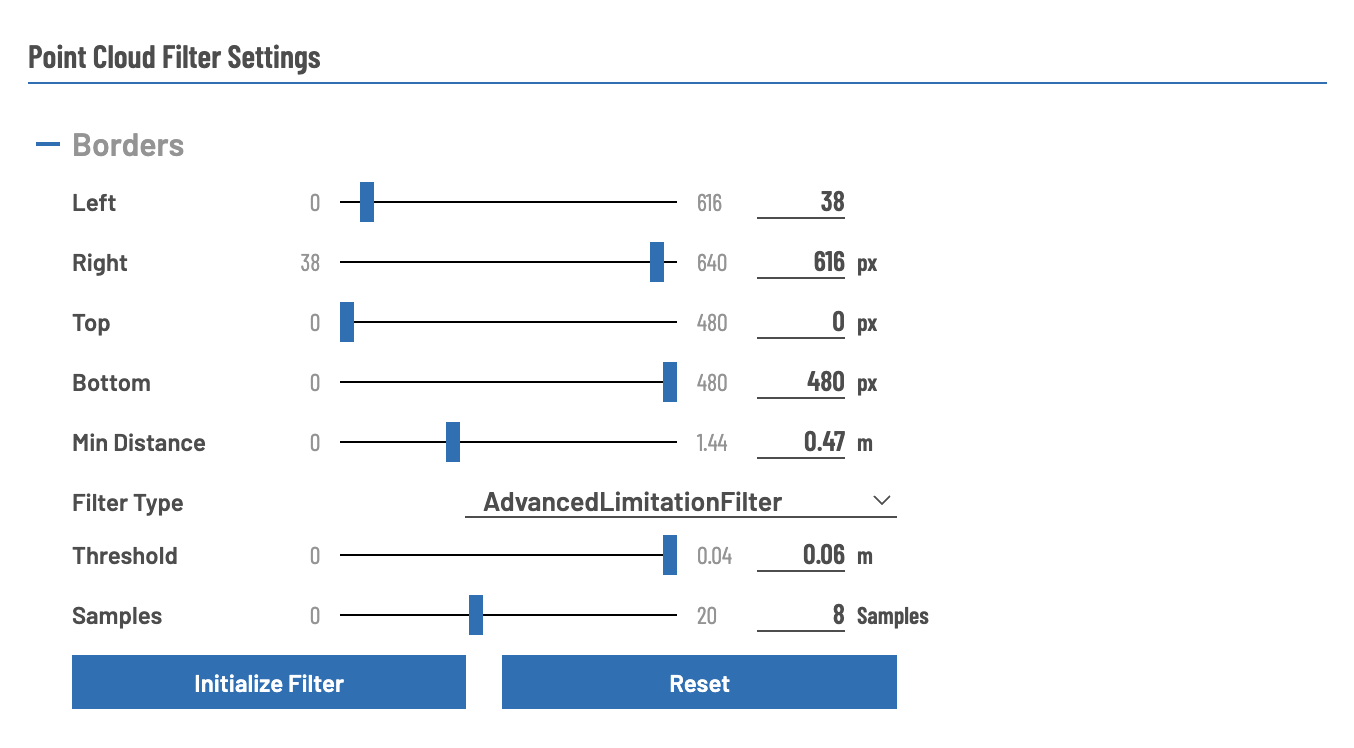
Borders
Settings that determine which parts of the point cloud are invalidated before filtering and processing steps. Most prominently used to trim point cloud in horizontal and vertical direction to eliminate areas that do not belong ro the interactive surface (e.g. parts of the frame)
| Setting | Value Range | Description | Unit |
|---|---|---|---|
| Left | [0, Right Border] | Specify how many depth points on the left side are ignored. Maximum value corresponds with the border filter value on the right side. Live Preview: red dots are filtered points. | Pixel (in the depth image) |
| Right | [Left Border, Frame Width] | Specify how many depth points on the right side are ignored. Minimum value corresponds with the border filter value on the left side. Live Preview: red dots are filtered points. | Pixel (in the depth image) |
| Top | [0, Bottom Border] | Specify how many depth points on the upper side are ignored. Maximum value corresponds with the border filter value on the lower side. Live Preview: red dots are filtered points. | Pixel (in the depth image) |
| Bottom | [Top Border, Frame Height] | Specify how many depth points on the lower side are ignored. Minimum value corresponds with the border filter value on the upper side. Live Preview: red dots are filtered points. | Pixel (in the depth image) |
| Min Distance | [0, 1.44] | Filter out points that are too close to the sensor (usually “dead points” or points outside the tracking frustum) | meters (from the sensor) |
| Threshold | [0, 0.1] | Specify maximum distance from zero plane for the points to be filtered | meters (from the zero plane) |
| Filter Type | - | Available limitation filters. LimitationFilter: filter based on the defined borders AdvancedLimitationFilter: filter based on the depth mask (additional to the borders) | - |
| Samples | [0, 20] | Specify how many samples from the depth image are captured for initializing the filter. | number |
REMARKS:
- Top, Bottom, Left, Right refer to the camera coordinate system and are not affected by Calibration. This means that these values may be mirrored in regard to the users perspective
- Before
Initialize Filter, it is recommended to deactivateBox Filterin Additional Settings
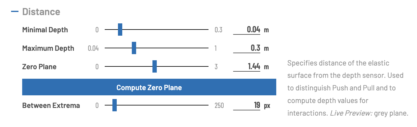
Distance
Basic configuration of the system: distance between sensor and fabric (zero plane), interaction space (maximum and minimum amplitude of deformation) and minimum distance between two touch points can be specified.
Zero plane can be computed automatically, which is done by measuring the mean distance of valid points (fabric must not be deformed for a precise measurement).
| Setting | Value Range | Description | Unit |
|---|---|---|---|
| Minimal Depth | [0, 0.3] | Specifies the minimal depth amplitude for both Push and Pull relative to the Zero Plane. Depth values smaller than this threshold are ignored for interaction processing. Live Preview: red planes. | meters (from the zero plane) |
| Maximum Depth | [0, 1] | Specifies the maximum depth amplitude for both Push and Pull relative to the Zero Plane. Depth values larger than this threshold are ignored for interaction processing. Live Preview: blue planes. | meters (from the zero plane) |
| Zero Plane | [0,3] | Specifies distance of the elastic surface from the depth sensor. Used to distinguish Push and Pull and to compute depth values for interactions. Live Preview: grey plane. | meters (from the sensor) |
| Between Extrema | [0, 250] | Threshold for lateral distance between two extremums in the depth image (pixel distance). Used to filter redundant interactions which may occur due to noise. | pixel between x,y coordinates of extrema |
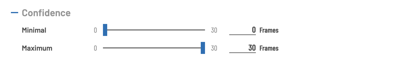
Confidence
Confidence describes to which extent an interaction is based on a measurement error (e.g. jitter) or can be categorized as stable touch detection. To compute the value, on each frame, the associated touch point is recognized, the confidence value is increased (to a maximum value specified by Maximum). When an interaction is not recognized anymore, the confidence value is decreased for every frame the interaction is not detected (until the confidence value is 0).
This prevents flickering in case a touch point is not recognized anymore by some frames, but also introduces a certain lag, as the interaction is still “valid” when not touching the display, until the confidence value falls below the Minimal value. The lag also occurs if the Minimal value is rather high, as the interaction needs to be detected for the number of consecutive frames, before the interaction is marked as valid.
| Setting | Value Range | Description | Unit |
|---|---|---|---|
| Minimal | [0, Maximum] | The minimal confidence for which the interaction is categorized as valid measurement | - |
| Maximum | [Minimum, 30] | The maximum confidence for an interaction. After reaching this value the confidence is not increased anymore | - |
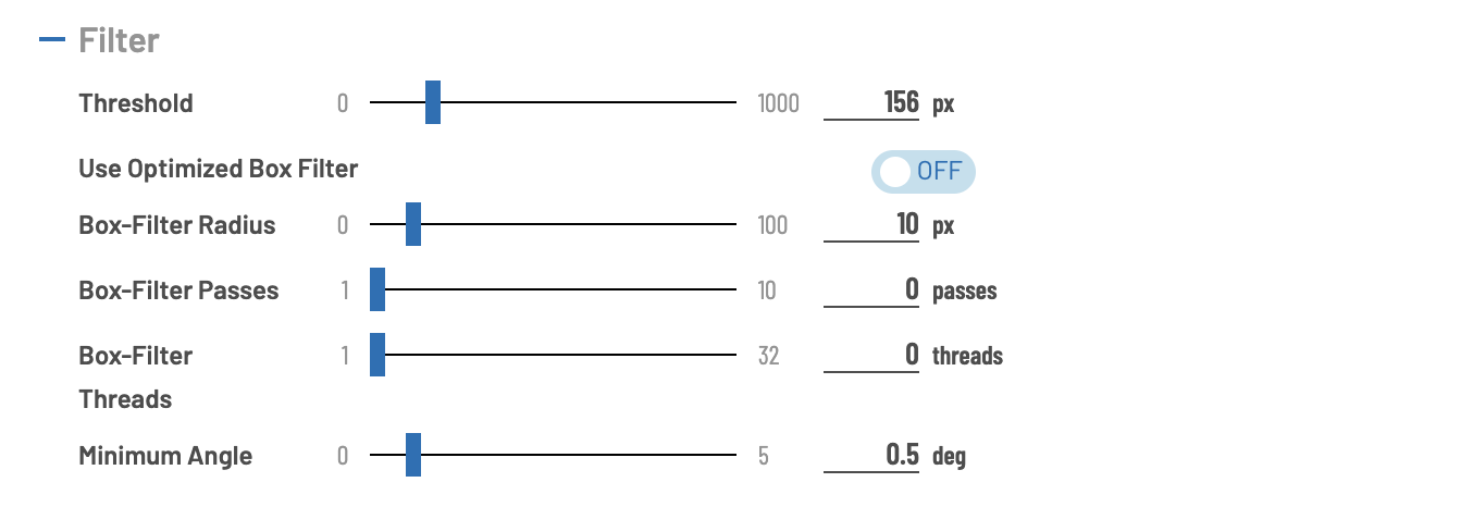
Filter
Settings in this section specify option for several aspects in regard of processing the point cloud derived from the depth image.
| Setting | Value Range | Description | Unit |
|---|---|---|---|
| Threshold | [0, 1000] | Used to filter outliers from depth image. Specifies the maximum depth difference between two adjacent points in the Pointcloud. Points which do not satisfy this condition are filtered. | (Pixel) Distance in z-direction between two pints |
| Use optimized Box Filter | on, off | Specifies whether standard or optimized box filter implementation should be used. Optimized version is faster in general | - |
| Box-Filter radius | [0,100] | The depth image is filtered using box-blur algorithm with the given radius for the filter. A very large radius results in a very smooth depth image, but only very sharp edges are detected. Additionally, the computational cost increases with radius size. | Pixel |
| Box-Filter passes | [0,10] | Number of iterations the box-blur is applied. A larger number of iterations results in a better filter result, but with decreased performance. | - |
| Box-Filter Threads | [0, 32] | Max Number of Threads to use for filtering. Best value is usually less or equal the number of logical processors. When providing 0, the system decides which is the best value, 1 means single core performance. |
- |
| Minimum angle | [0, 5] | Minimum angle between neighboring vectors for extremum detection. Used to filter low frequency noise. | Degrees |
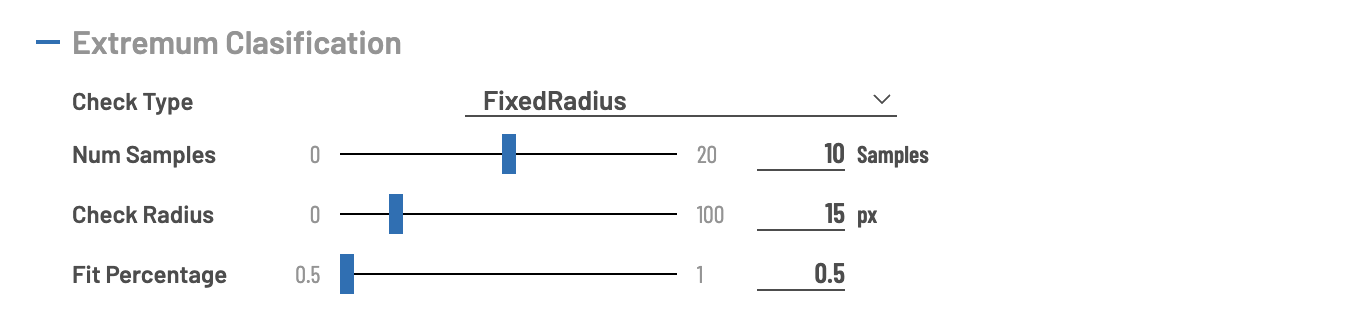
Extremum Classification
Detected extrema are classified (local minimum, local maximum or undefined) based on the depth values of the neighboring pixels. There are different algorithms available:
- Global: basically disable the check: depth value below 0.5 means minimum, above maximum.
- FixedRadius: check a predefined number of positions in a given radius
- StochasticStatic: check random positions (determined on program start)
- StochasticDynamic: check random positions (determined for each frame on each extremum)
| Setting | Value Range | Description | Unit |
|---|---|---|---|
| Num Samples | [0, 20] | The number of samples which are used to check the extremum type. 0 means that no check is executed. | - |
| Check Radius | [0, 100] | The pixel radius in which points are sampled to check the type of the extremum. | Pixel in the depth image |
| Fit percentage | [0.5, 1.0] | The ratio to discriminate whether a distinct extremum type is detected. | The ratio of pixels with lower vs. higher depth value |
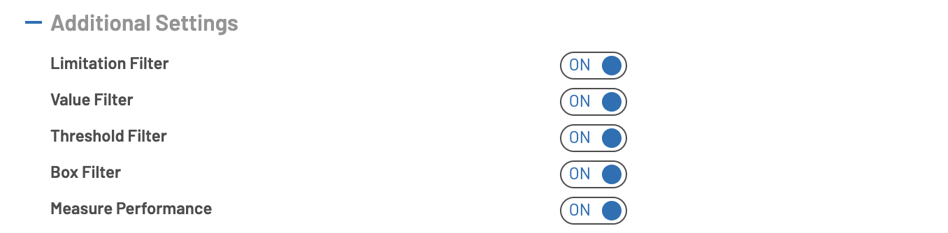
Additional Settings
Toggles for enabling / disabling different filters for point cloud processing and the switch to enable/disable performance measurements (which activates / deactivates Performance Visualization)
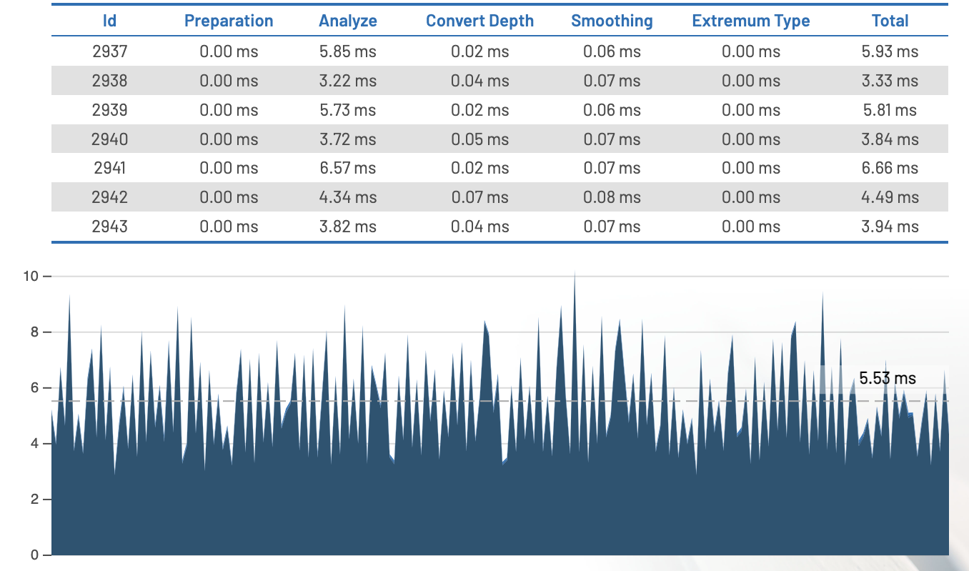
Performance Visualization
![]()